
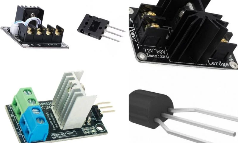
Mosfets and Making Robustness Control
Mosfets, defined as electronic switches with various functions depending on their areas of use, have existed since the early 1920s, but their actual use had to wait until the 1960s. These components, which have 4 different types, have two main models. These models are referred to as N-channel and P-channel. These channels are related to the polarity voltage. The options, which also have two different subtypes, appear as enhancement and depletion mosfet options. There is an insulating region between the gate terminal of the mosfets and the other two terminals.
Controlling Gate Voltage in Mosfets
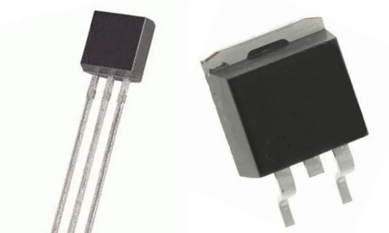
It is possible to control the gate voltage through the Drain-Source resistance in mosfets. These systems, which do not have Collector-Emitter voltage drops, are also similar to resistors in terms of their properties. There is no need to exert any effort to access mosfet options that appear in various industrial applications as voltage-controlled resistor elements. Anyone who wants to procure products in the electronics field can meet their needs through the relevant online stores on internet pages. There are also some tests to perform robustness control of the system. Today, since most multimeters have a diode test setting, it is possible to ensure control. During the control phase, a test voltage of approximately 4V is required for the test.
Sufficient Voltage to Trigger a Mosfet
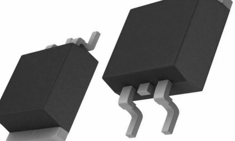
After accessing the sufficient test voltage for the robustness control of the mosfets, the measuring instrument must be set to the resistance position. Then, the probe is touched to the drain pin. Simultaneously, the probe must also be touched to the source pin. After this operation, the obtained value should be approximately zero. The same value is expected to occur if the probes are interchanged. In another testing method, the positive probe should be touched to the drain pin and the negative probe to the gate pin, and accordingly, the resistance value is expected to be read around 7-8.